|
ATLAS 350-XL RESTORATION | |
This article is in progress.
INTRODUCTUION
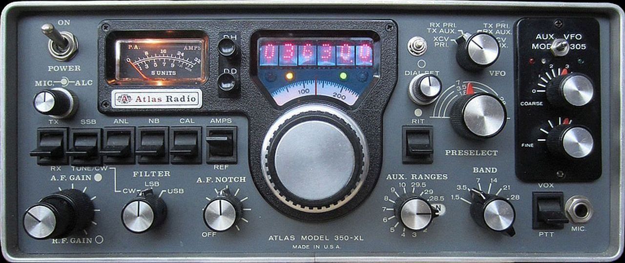
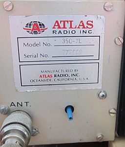
For a bargain price an ATLAS 350-XL from July 20, 1977 came into my possession. This type of transceiver probably sold only 1000 units for $999 in 1977. In the USA they had a good middle class car for that price at the time. Unlike the hybrid Japanese amateur transceivers with tubes in the output stage, this set featured two transistor amplifiers coupled together with combiners to produce a total of approximately 180 W ouput power.
Initially deployed in an airplane as a means of communication, the device is still packed with crystals for use outside the amateur bands.
The number of previous owners is unknown, but various repairs or modifications were made without accompanying documentation. In the power amplifier PC-550 POWER AMPLIFIER they installed 4 × SRF3795 which are fortunately still intact. Apparently something had gone wrong in the PC-540 PRE-DRIVER SWR PROTECT, because the toroidal 4 : 1 transformer was replaced by a type with two ferrite pipes and with other components mounted above the PCB as a kind of haystack circuit. Changes were also made on other boards. There is also a built-in Huff and Puff stabilizer for the VFO and the push button for it can be seen at the top right of the digital scale. Furthermore, many American Parker screws were missing.
LOUDSPEAKER & PARKER
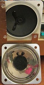
The cone of the speaker was apparently damaged more often during maintenance and then repaired with lacquer or glue. The first renovation was therefore to find a new one. Unfortunately, only round copies were for sale, so a rectangular frame was made from copper-free epoxy board to glue the speaker on.
Instead of the missing USA self-tapping screws, they are replaced by 3 mm screws by tapping a 3 mm screw thread.
PRE-DRIVER PC-540, DRIVER PC-530
|
I have restored the original pre-driver design, but installed a 2N5109 for Q502 and mounted a new toroidal 4 : 1 transformer L501. |
 |
It is also possible that emitter of Q503 is connected to ground with two 1.1 Ohm resistors connected in parallel.
During testing it appeared that without control in the SSB mode a considerable current was flowing. It took a while to find the cause, but it was due to the driver oscillating in combination with Q503 (2N3866) from the pre-driver. Apparently this transistor had already been replaced once and a 2N5109 was also mounted in its place as an experiment. Now the driver was only oscillating on a few bands. This was remedied by feedback from collector to base of the driver transistor Q532. With a 560 Ohm resistor and 100 nF capacitor, the driver remained stable.
POWER AMPLIFIER PC-550
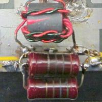
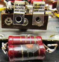
In the power amplifier PC-550, resistor R558, 220 Ohm/3 W, was blackened and only 188 Ohm. This has now been replaced by two 100 Ohm/30 W induction-free resistors in series. The resistors are not mounted on a heat sink, but the required 3 W dissipation is well approximated by the cooling fins.
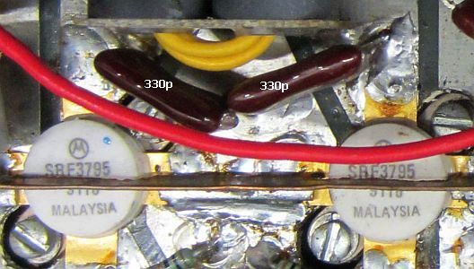
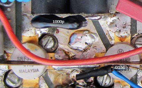
Because here a lot of experience has been gained with HF transistor power amplifiers, it seemed a good idea to follow the advice on the internet to remove the 330 pF capacitors (C556, C557, C562, C563) across the collectors and replace them with one 1000 pF capacitor across T554 and T557. That also was a great opportunity to change the feed connection via both transformers and supply it with two extra bifilar coils as can be seen in the diagram above.
Furthermore, the diodes D551 and D552 were each mounted on one of the pairs SRF3795 so that they follow the temperature of the transistors as closely as possible.
The power has now increased by about 20 W at 20 m to 160 m. Only at 15 and 10 m it remains below 100 W, the why has not yet been found.
Due to the measures mentioned, the output has increased considerably. Only at 10 and 15 m it remained on the low side; the why has not yet been found.
![]()